Product Description
Product Description
Hot Selling GL Type Spline Rigid Shaft Couplings Roller Chain Coupling For Industry Machine
FEATURES
Manufactured according to relevant industrial standards
Available in many sizes, ratings, and product types, including flexible shaft couplings and OK couplings
Fabricated from a variety of high-grade steel
BENEFITS
Several surface treatment processes protect against corrosion
Customized products are available
Large couplings withstand very high torque
Flexible shaft couplings compensate for shaft misalignment
The chain coupling consists of two-strand roller chains, 2 sprockets and AL-Alloy cover, features simple and compact structure, and high flexibility, power transmission capability and durability.
What’s more ,the chain coupling allows simple connection/disconnection, and the use of the housing enhances safety and durability.
The number of roller depends CHINAMFG the specific application
| Chain No. | Pitch
P mm |
Roller diameter d1max mm |
Width between inner plates b1min mm |
Pin diameter d2max mm |
Pin length | Inner plate depth h2max mm |
Plate thickness
Tmax mm |
Tensile strength
Qmin kN/lbf |
Average tensile strength
Q0 |
Weight per meter q kg/m |
|
| Lmax
mm |
Lcmax
mm |
||||||||||
| 08AF36 | 12.700 | 7.95 | 21.70 | 3.96 | 30.8 | 32.1 | 12.00 | 1.50 | 13.8/3135.36 | 16.20 | 1.070 |
| 10AF13 | 15.875 | 10.16 | 16.31 | 5.08 | 27.6 | 29.1 | 15.09 | 2.03 | 22.2/5045 | 27.50 | 1.350 |
| 10AF71 | 15.875 | 10.16 | 19.00 | 5.08 | 30.5 | 32.2 | 15.09 | 2.03 | 21.8/4901 | 24.40 | 1.480 |
| *10AF75 | 15.875 | 10.16 | 45.60 | 5.08 | 57.0 | 58.5 | 15.09 | 2.03 | 21.8/4901 | 24.40 | 2.540 |
| 12AF2 | 19.050 | 11.91 | 19.10 | 5.94 | 32.6 | 34.4 | 18.00 | 2.42 | 31.8/7227 | 38.20 | 1.900 |
| 12AF6 | 19.050 | 11.91 | 18.80 | 5.94 | 31.9 | 33.5 | 18.00 | 2.42 | 31.8/7227 | 38.20 | 1.870 |
| 12AF26 | 19.050 | 11.91 | 19.36 | 5.94 | 31.9 | 33.5 | 18.00 | 2.42 | 31.8/7227 | 38.20 | 1.940 |
| 12AF34 | 19.050 | 11.91 | 19.00 | 5.94 | 31.9 | 31.9 | 18.00 | 2.42 | 31.1/7066 | 38.20 | 1.860 |
| 12AF54 | 19.050 | 11.91 | 19.50 | 5.84 | 31.9 | 31.9 | 18.00 | 2.29 | 31.1/7066 | 38.20 | 1.607 |
| *12AF97 | 19.050 | 11.91 | 35.35 | 5.94 | 48.8 | 50.5 | 18.00 | 2.42 | 31.8/7149 | 38.20 | 2.630 |
| *12AF101 | 19.050 | 11.91 | 37.64 | 5.94 | 51.2 | 52.9 | 18.00 | 2.42 | 31.8/7149 | 38.20 | 1.990 |
| *12AF124 | 19.050 | 11.91 | 20.57 | 5.94 | 33.9 | 35.7 | 18.00 | 2.42 | 31.8/7149 | 38.20 | 1.910 |
| 16AF25 | 25.400 | 15.88 | 25.58 | 7.92 | 42.4 | 43.9 | 24.00 | 3.25 | 56.7/12886 | 63.50 | 3.260 |
| *16AF40 | 25.400 | 15.88 | 70.00 | 7.92 | 87.6 | 91.1 | 24.00 | 3.25 | 56.7/12886 | 63.50 | 5.780 |
| *16AF46 | 25.400 | 15.88 | 36.00 | 7.92 | 53.3 | 56.8 | 24.00 | 3.25 | 56.7/12886 | 63.50 | 3.880 |
| *16AF75 | 25.400 | 15.88 | 56.00 | 7.92 | 73.5 | 76.9 | 24.00 | 3.25 | 56.7/12746 | 63.50 | 5.110 |
| *16AF111 | 25.400 | 15.88 | 45.00 | 7.92 | 62.7 | 65.8 | 24.00 | 3.25 | 56.7/12746 | 63.50 | 4.480 |
| *16AF121 | 25.400 | 15.88 | 73.50 | 7.92 | 91.3 | 94.7 | 24.00 | 3.25 | 56.7/12746 | 63.50 | 6.000 |
*The number of roller depends CHINAMFG the specific application
| Chain No. | Pitch P mm |
Roller diameter d1max mm |
Width between inner plates b1min mm |
Pin diameter d2max mm |
Pin length | Inner plate depth h2max mm |
Plate thickness
Tmax mm |
Tensile strength
Qmin kN/lbf |
Average tensile strength
Q0 kN |
Weight per meter q kg/m |
|
| Lmax
mm |
Lcmax
mm |
||||||||||
| *20AF44 | 31.750 | 19.05 | 32.00 | 9.53 | 53.5 | 57.8 | 30.00 | 4.00 | 86.7/19490 | 99.70 | 4.820 |
| *24AF27 | 38.100 | 22.23 | 75.92 | 11.10 | 101.0 | 105.0 | 35.70 | 4.80 | 124.6/28571 | 143.20 | 9.810 |
| *06BF27 | 9.525 | 6.35 | 18.80 | 3.28 | 26.5 | 28.2 | 8.20 | 1.30 | 9.0/2045 | 9.63 | 0.770 |
| *06BF31 | 9.525 | 6.35 | 16.40 | 3.28 | 23.4 | 24.4 | 8.20 | 1.30 | 9.0/2045 | 9.63 | 0.660 |
| *06BF71 | 9.525 | 6.35 | 16.50 | 3.28 | 24.5 | 25.6 | 8.20 | 1.30 | 9.0/2571 | 9.63 | 0.830 |
| 08BF97 | 12.700 | 8.51 | 15.50 | 4.45 | 24.8 | 26.2 | 11.80 | 1.60 | 18.0/4989.6 | 19.20 | 0.980 |
| *08BF129 | 12.700 | 8.51 | 35.80 | 4.45 | 45.1 | 46.1 | 11.80 | 1.60 | 18.0/4989.6 | 19.02 | 1.500 |
| 10BF21 | 15.875 | 10.16 | 42.83 | 5.08 | 52.7 | 54.1 | 14.70 | 1.70 | 22.0/5000 | 25.30 | 2.260 |
| 10BF43 | 15.875 | 7.03 | 27.80 | 5.08 | 39.0 | 40.6 | 14.70 | 2.03 | 22.4/5090 | 25.76 | 1.140 |
| *10BF43-S | 15.875 | 10.00 | 27.80 | 5.08 | 39.0 | 40.6 | 14.70 | 2.03 | 22.4/5090 | 25.76 | 1.800 |
| *16BF75 | 25.400 | 15.88 | 27.50 | 8.28 | 47.4 | 50.5 | 21.00 | 4.15/3.1 | 60.0/13488 | 66.00 | 3.420 |
| *16BF87 | 25.400 | 15.88 | 35.00 | 8.28 | 54.1 | 55.6 | 21.00 | 4.15/3.1 | 60.0/13488 | 66.00 | 3.840 |
| *16BF114 | 25.400 | 15.88 | 49.90 | 8.28 | 69.0 | 72.0 | 21.00 | 4.15/3.1 | 60.0/13488 | 66.00 | 4.740 |
| *20BF45 | 31.750 | 19.05 | 55.01 | 10.19 | 76.8 | 80.5 | 26.40 | 4.5/3.5 | 95.0/21356 | 104.50 | 6.350 |
| *24BF33 | 38.100 | 25.40 | 73.16 | 14.63 | 101.7 | 106.2 | 33.20 | 6.0/4.8 | 160.0/35968 | 176.00 | 11.840 |
Advantages:
1. Material: C45 steel, Aluminum, Rubber and plastic etc.
2. High efficiency in transmission
3. Finishing: blacken, phosphate-coat, and oxidation.
4. Different models suitable for your different demands
5. Application in wide range of environment.
6. Quick and easy mounting and disassembly.
7. Resistant to oil and electrical insulation.
8. Identical clockwise and anticlockwise rotational characteristics.
9. Small dimension, low weight, high transmitted torque.
10. It has good performance.
| Partnerships Reliable Supply-Chain: |
Based on our experienced team and strict, effective supply chain management, Granville products deliver premium quality, and performance our customers have relied on for years. From a full range of bearings, mounted bearing units, power transmission products, and related markets around the world, we provide the industry’s most comprehensive range of qualified products available today.
Advantage Manufacturing Processesand Quality Control:
01 Heat Treatment
02 Centerless Grinding Machine 11200 (most advanced)
03 Automatic Production Lines for Raceway
04 Automatic Production Lines for Raceway
05 Ultrasonic Cleaning of Rings
06 Automatic Assembly
07 Ultrasonic Cleaning of Bearings
08 Automatic Greasing, Seals Pressing
09 Measurement of Bearing Vibration (Acceleration)
10 Measurement of Bearing Vibration (Speed)
11 Laser Marking
12 Automatic Packing
1 Prevent from damage.
2. As customers’ requirements, in perfect condition.
3. Delivery : As per contract delivery on time
4. Shipping : As per client request. We can accept CIF, Door to Door etc. or client authorized agent we supply all the necessary assistant.
FAQ
Q 1: Are you a trading company or a manufacturer?
A: We are a professional manufacturer specializing in manufacturing various series of couplings.
Q 2:Can you do OEM?
Yes, we can. We can do OEM & ODM for all the customers with customized artworks in PDF or AI format.
Q 3:How long is your delivery time?
Generally, it is 20-30 days if the goods are not in stock. It is according to quantity.
Q 4: How long is your warranty?
A: Our Warranty is 12 months under normal circumstances.
Q 5: Do you have inspection procedures for coupling?
A:100% self-inspection before packing.
Q 6: Can I have a visit to your factory before the order?
A: Sure, welcome to visit our factory.
/* January 22, 2571 19:08:37 */!function(){function s(e,r){var a,o={};try{e&&e.split(“,”).forEach(function(e,t){e&&(a=e.match(/(.*?):(.*)$/))&&1
| Standard Or Nonstandard: | Standard |
|---|---|
| Shaft Hole: | as Required |
| Torque: | as Required |
| Bore Diameter: | as Required |
| Speed: | as Required |
| Structure: | Flexible |
| Samples: |
US$ 1/Piece
1 Piece(Min.Order) | |
|---|
| Customization: |
Available
| Customized Request |
|---|
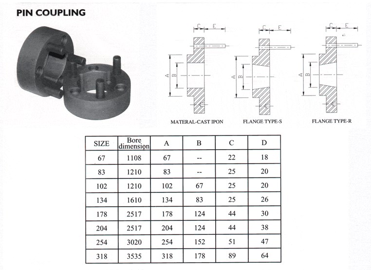
How Do Pin Couplings Compare to Other Types of Couplings in Terms of Performance?
Pin couplings offer certain advantages and disadvantages compared to other types of couplings, and their performance characteristics can vary depending on the specific application requirements. Below is a comparison of pin couplings with some commonly used couplings:
1. Gear Couplings:
- Flexibility: Gear couplings are more rigid than pin couplings and may not offer the same level of misalignment capacity.
- Torsional Stiffness: Gear couplings provide higher torsional stiffness, making them suitable for applications requiring precise torque transmission.
- Shock Absorption: Gear couplings can handle higher shock loads due to their robust design and greater stiffness.
- Maintenance: Gear couplings may require periodic lubrication and maintenance compared to maintenance-free pin couplings.
- Applications: Gear couplings are commonly used in heavy-duty and high-torque applications where precise torque transmission is essential.
2. Flexible (Elastomeric) Couplings:
- Flexibility: Elastomeric couplings offer higher misalignment capacity than pin couplings and can handle angular, parallel, and axial misalignment.
- Shock Absorption: Elastomeric couplings provide excellent shock absorption, damping vibrations, and protecting connected equipment.
- Torsional Stiffness: Elastomeric couplings have lower torsional stiffness compared to pin couplings, making them more forgiving in high shock load applications.
- Installation: Elastomeric couplings are easy to install and require no lubrication, making them maintenance-free.
- Applications: Elastomeric couplings are commonly used in pumps, compressors, and other machinery where vibration isolation is crucial.
3. Rigid Couplings:
- Torsional Stiffness: Rigid couplings provide high torsional stiffness, ensuring accurate torque transmission.
- Misalignment Capacity: Rigid couplings have little to no misalignment capacity and require precise shaft alignment.
- Applications: Rigid couplings are used in applications where precise alignment is essential, such as shaft-to-shaft connections in high-precision systems.
Conclusion:
Pin couplings strike a balance between flexibility and torsional stiffness, making them suitable for applications with moderate misalignment and shock loads. They are often used in general industrial applications, conveyors, and light to medium-duty machinery.
When selecting a coupling for a specific application, it is crucial to consider factors such as misalignment requirements, shock and vibration loads, torsional stiffness, maintenance needs, and the level of precision required. Each coupling type has its strengths and weaknesses, and the appropriate choice will depend on the specific demands of the application.
Can Pin Couplings Be Used for Both Motor-to-Shaft and Shaft-to-Shaft Connections?
Yes, pin couplings can be used for both motor-to-shaft and shaft-to-shaft connections in various mechanical systems. The versatile design of pin couplings allows them to connect two shafts with aligned or misaligned centers, making them suitable for a wide range of applications.
Motor-to-Shaft Connections: In motor-driven systems, pin couplings are commonly used to connect the motor shaft to the driven shaft of the equipment. The motor can be an electric motor, combustion engine, or any other type of power source. The pin coupling efficiently transfers torque from the motor shaft to the equipment’s driven shaft, enabling power transmission and mechanical motion.
Shaft-to-Shaft Connections: Pin couplings are also well-suited for shaft-to-shaft connections, where two separate shafts need to be joined together. This could be the case when extending the length of a shaft or connecting two separate pieces of rotating equipment. The pin coupling provides a secure and flexible connection between the two shafts, allowing torque to be transmitted between them while accommodating misalignment.
It is essential to consider the specific requirements of the application when selecting a pin coupling. Factors such as the amount of misalignment, torque capacity, operating conditions, and space constraints should be taken into account to ensure the coupling can effectively and reliably connect the motor and shafts.
Overall, the versatility and performance of pin couplings make them a popular choice for both motor-to-shaft and shaft-to-shaft connections in various industrial and mechanical systems.
Can Pin Couplings Handle Misalignment Between Shafts?
Yes, pin couplings are designed to accommodate a certain degree of misalignment between shafts in rotating machinery. They are considered flexible couplings, which means they can provide some degree of angular, parallel, and axial misalignment capability.
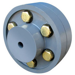
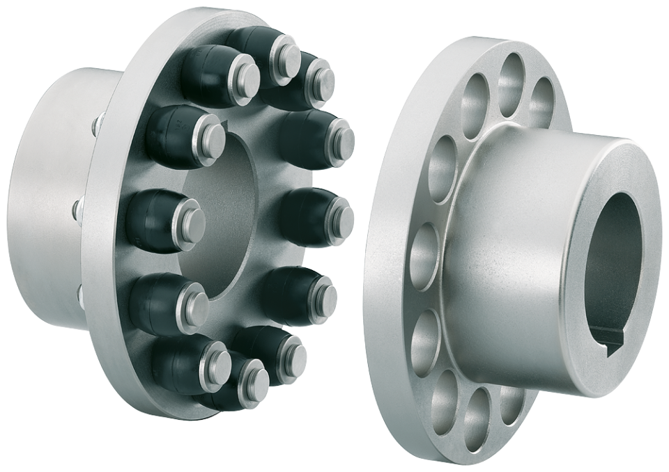
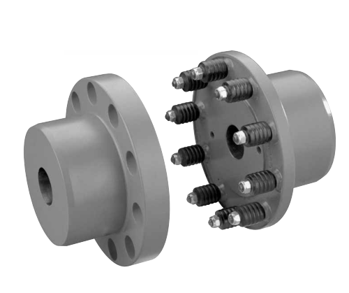
Pin couplings typically consist of two hubs, each connected to a shaft, and a central sleeve with pins that transmit torque between the hubs. The pins allow for a limited range of movement, which helps to compensate for slight misalignments between the shafts.
The angular misalignment capacity of a pin coupling is achieved through the bending of the pins. When the shafts are misaligned at an angle, the pins on one side of the coupling experience bending while those on the opposite side are in tension. The pins are designed to withstand these bending and tension forces within their elastic limits, ensuring proper functioning and longevity of the coupling.
Similarly, the pins can accommodate parallel misalignment by sliding within the pin holes of the coupling’s central sleeve. This sliding action allows the hubs to move slightly relative to each other, compensating for any offset between the shafts.
However, it is essential to note that pin couplings have limitations in terms of the amount of misalignment they can handle. Excessive misalignment beyond their specified limits can lead to increased wear on the pins and other coupling components, reducing the coupling’s effectiveness and potentially causing premature failure.
While pin couplings are suitable for applications with moderate misalignment requirements, they may not be the best choice for applications with significant misalignment or where precise alignment is critical. In such cases, more flexible couplings like gear or elastomeric couplings may be more appropriate.
Overall, when considering the use of pin couplings, it is essential to carefully evaluate the specific misalignment requirements of the application and select a coupling that can adequately accommodate those misalignments while ensuring reliable and efficient power transmission.


editor by CX 2024-04-10
by
Tags:
Leave a Reply